
Remove all unused/obsolete ship's wiring, repair as req'd
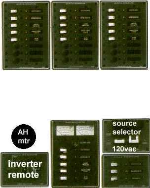
Proposed layout:
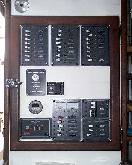
and what it ended up looking like....
clik on pix to ENLARGE
While it's somewhat difficult using this media to show the extent of the work done on this particular job, these before and after photos will provide the viewer a pretty good idea on what was accomplished.
What you're looking at here on the right is our finished product, utilizing
Blue Sea Systems breaker panels, who also sell an extensive
Label set, a WestMarine Ultra Alarm (for high bilge water),
Heart Link10
battery monitoring system,
an existing
Heart Inverter Remote Control for operation of the 2500watt Heart Inverter was incorporated into the layout, but they also make the
Heart Link1000 Remote/Monitor combo, which might work out better for a limited-space situation.
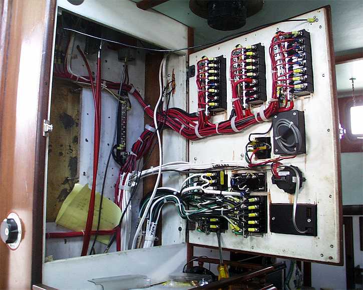
As previously mentioned, existing wiring was used where practical, but a lot of it was replaced with
Ancor Marine Grade Wire
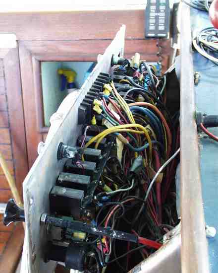
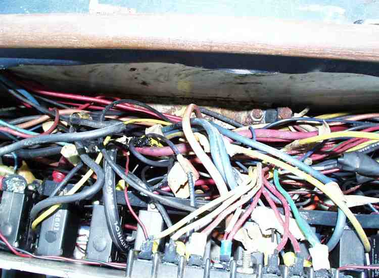
At this point, it's a good idea to get a look at
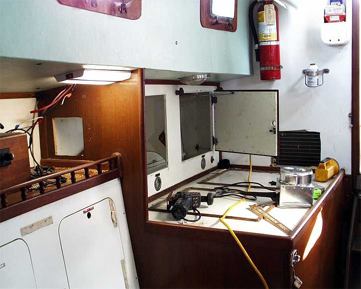
The Before Views,
Also to be noted is the
American Boat & Yacht Council (ABYC) recommended
and then on to the next phase:
Relocate genset to engine room, relocate and re-pipe reefer unit
This was an 'interesting installation' - to be sure - especially considering where the AC units needed to be located, never mind the 1/8" steel bulkheads - but this is another chapter....
utilize existing wiring where practical, rewire as necessary.
Reconfigure primary circuit (battery wiring) and install monitoring system
Relocate/consolidate house wiring and controls from helm console to cabin
Design & layout of new main breaker panel in galley area
DC w 24 breakers on TOP -- AC system w 8 breakers on bottom
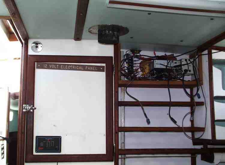
The original electrical system layout had part of the system (aux/house functions) located here
inside this cabinet, with the rest of it ('boat' functions) located at/inside the
helm console -
which initially may have been a good idea, but devolved into the
typical rats nest -
which is why the decision was made to relocate most of it here...
so you get a full appreciation of what this job really entailed...
 As you can see, things are quite a bit improved....
with each function on it's own separate circuit breaker/switch,
all located at one panel, which allows the Skipper to ascertain the status of the system AT A GLANCE, with easy access to the backside for any future changes, additions or repairs.
On the lower-left of this shot, the Battery Main-Selector switch is visible at it's new, easy to get at AND monitor location
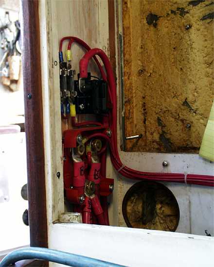 While the previous installation involved the use of 2 different switches - inside the cabinet, plus 1 in the engine room - the new configuration has just one.
(plus an engine-battery disconnect). This allows a simple, quick'n'easy paralleling of the house and engine batteries if necessary. It's location also allows the operator of the vessel to ascertain
While the previous installation involved the use of 2 different switches - inside the cabinet, plus 1 in the engine room - the new configuration has just one.
(plus an engine-battery disconnect). This allows a simple, quick'n'easy paralleling of the house and engine batteries if necessary. It's location also allows the operator of the vessel to ascertain
AT A GLANCE whether or not the banks are combined. In normal operation, this switch remains in the house(#2) position - it's only necessary to change it if the engine can't be cranked on it's own separately-connected&switched battery.
Over Current Protection, something the previous system was dangerously deficient on.
then install 2 ducted AC units - 1 for the main cabin, 1 aft.

Please Email
or Call: 808.754.2082
 ElectroMarine Services
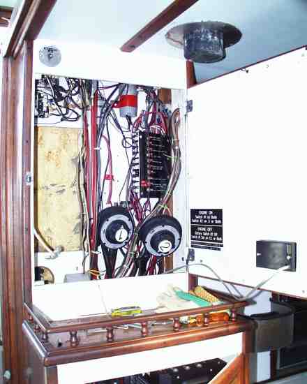